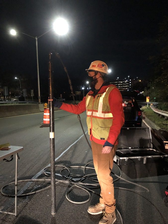
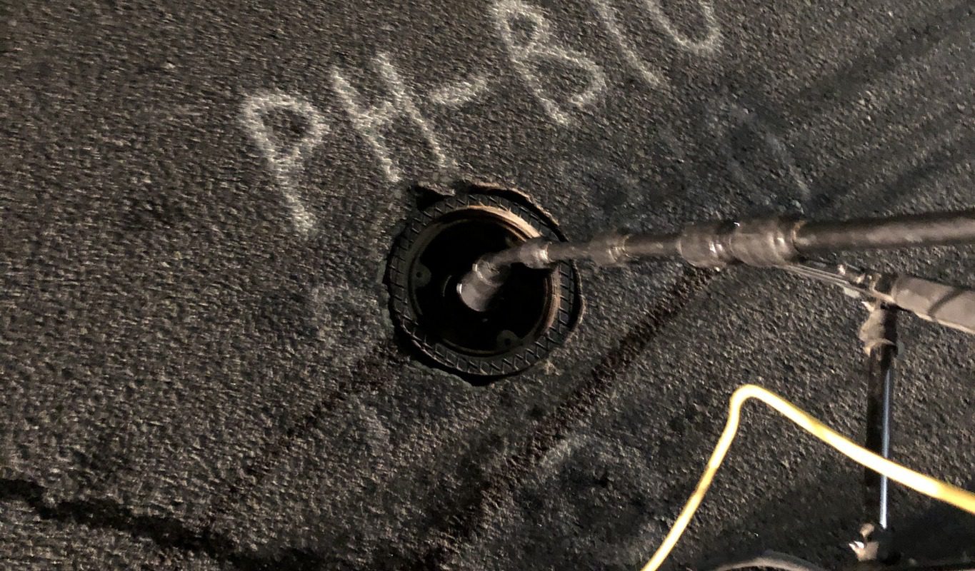
Borehole Ground Penetrating Radar
This method applies all the same principles of GPR but uses a modified GPR antenna designed specifically to work in large- or small-diameter borings. The systems must be used in either uncased borings or PVC-cased drill holes, as the instrument cannot transmit a signal through steel casing. The borehole GPR antenna is designed to image sideways from the borehole to map surrounding features in the soil, rock or man-made structure(s). The method can be used in either a single boring with omni-directional imaging (i.e., 360-degree view with no directionality), or pairs of borings to perform crosshole GPR tomography imaging. The latter is much more sophisticated and provides greater resolution and image reconstruction; whereas single borehole GPR can have the limitation of not knowing where the EM signal is being reflected from (directionally). BH-GPR applications include: soil profile imaging, karst, imaging of embedded concrete or steel (e.g., piles) structures, fault identification, quantification of fracture density and orientation in rock, and detection of other utility-like features (pipes, tanks, etc.). The method works the same as standard GPR, by measuring the reflection time and amplitude of EM wave pulses transmitted and received in the single borehole instrument. Typical antenna center frequencies include 100 MHz (high lateral penetration and lower resolution) and 1,000 MHz (low lateral penetration with high resolution).
Applicable On:
Soil
Rock
NDT Applications (Pile Tip Depth, Shaft Integrity, Etc.)
Test For:
Geologic Features
Man-Made Obstructions or Embedments
Structural, Pavement, & Tunnel Methods
Foundation Depth & Integrity Methods
Geophysical Methods
Seismic
Electrical Resistivity
Electromagnetics
Ground Penetrating Radar