Asphalt Thickness Evaluation
PURPOSE
A Nondestructive Testing (NDT) investigation was performed on asphalt highway slabs in Colorado.
OBJECTIVE
The objective of the investigation was to calculate the average asphalt thickness in the areas of interest on three state highways.
METHOD
Ground Penetrating Radar (GPR).

DATA ACQUISITION
Data acquisition was accomplished by a two-man crew over the course of two days. Scans were taken in each direction of the approximate 36 miles of road resulting in 72 miles of data. A truck-mounted Ground Penetrating Radar system was used for high speed data collection. Data was collected using 2 radar antennas, including an 800 MHz antenna and a 2.3 GHz antenna. The 800MHz antenna is lower frequency and used for deep penetration and the 2.3 GHz antenna is used for shallow depth penetration. The GPS location data was collected with an external GPS GNSS antenna.
INTERPRETATION
The GPR method involves moving an antenna across a test surface while periodically sending pulsed waveforms from the antenna and recording the received echoes. These electromagnetic wave pulses propagate through the material directly under the antenna, with some energy reflecting back whenever the wave encounters a change in electrical impedance, such as at a section of rebar or other steel embedment or asphalt/subgrade interface. The antenna then receives these echoes, which are amplified and filtered in the GPR computer, and then digitized and stored. A distance wheel records scan distance across the test surface and embedded features can be located at a given distance from the scan start position.
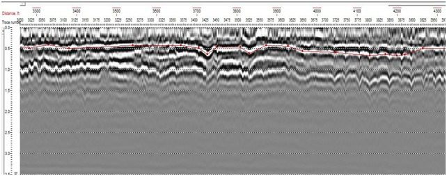
The resulting raw data is in the form of echo amplitude versus time. By inputting the dielectric constant, which defines the material velocity, and by estimating the signal zero point, the echo time data can be converted to echo depth. The scans are then typically plotted as two-dimensional (2D) waterfall plots of all of the individual data traces collected, with the lightness or darkness of each point in the plot being set by the amplitude and polarity (positive or negative) of the data at a given depth in each trace. A typical data plot identifying asphalt pavement thickness and depth of sub-base is shown here.


RESULTS
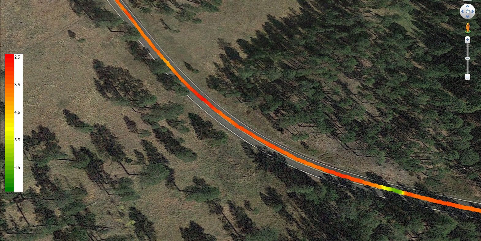
The results of the evaluation were plotted and overlain on a Google Earth map with ‘cool’ colors (e.g., green) representing thicker asphalt and ‘warm’ colors (e.g., red) representing thinner asphalt.
