Dam Spillway Evaluation
PURPOSE
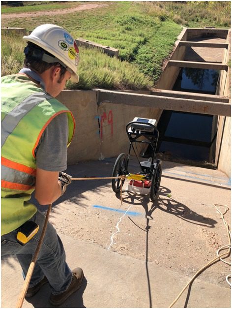
Olson Engineering performed a Nondestructive Testing (NDT) evaluation of a dam spillway in Colorado.
OBJECTIVE
The objective of the investigation was to verify the thickness and condition of the concrete spillway, as well as to locate any potential voids immediately below the concrete.
METHOD
The Impact Echo (IE) test method was used to measure concrete thickness and to assess the overall condition of the concrete. The Ground Penetrating Radar (GPR) test method was used to verify the presence of reinforcing steel and to locate any potential voids beneath the concrete slabs.
GPR Testing

DATA ACQUISITION
One day of fieldwork was performed by one engineer.
The IE testing was performed on a 4 ft x 5 ft grid which resulted in 245 IE data points on the spillway. The IE method involves impacting the concrete surface and identifying the reflected wave energy with a displacement or accelerometer receiver mounted on the surface near the impact point. The IE testing was performed using an Olson Instruments NDE-360 and IE-1 test head with a 2oz steel ball peen hammer as the energy source. An IE velocity of 12,000 ft/sec was used for thickness calculations.
The GPR testing was performed using both a 400 MHz and 1600 MHz antenna. The GPR method involves moving an antenna across the test surface while periodically sending pulsed waveforms from the antenna and recording the received echoes. Scans were performed longitudinally at 4 foot intervals across the spillway. The test layout resulted in approximately 1,150 linear feet of GPR scanning with each antenna.
INTERPRETATION
Impact Echo (IE): The thickness of the spillway slabs ranged from 5.6 to 33.8 inches. The two figures shown here present example IE test data records from the concrete spillway. Note the clear, single frequency peak, indicating sound, well-bonded concrete in the first figure versus multiple peaks indicating delamination in the second figure.
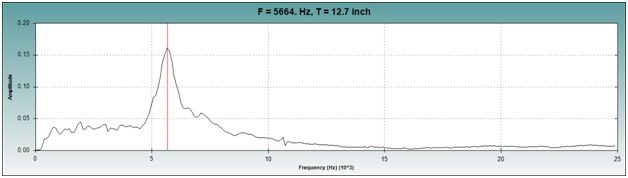
IE Test Record showing clear peak at 12.7 inches
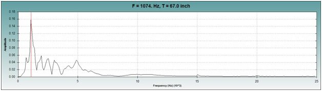
IE Test Record indicating delamination
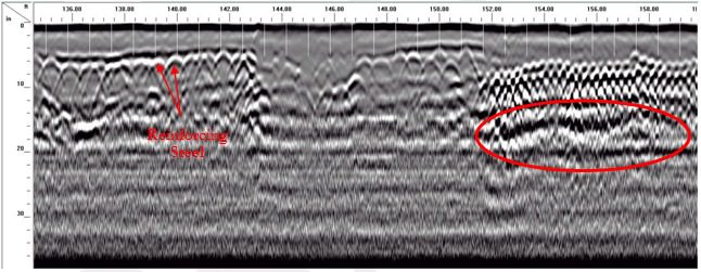
Ground Penetrating Radar (GPR): The GPR results identified reinforcing steel at inconsistent spacing, shown here on the left side of the figure. The GPR results also identified a number of questionable subgrade conditions that are commonly associated with voids beneath slabs. An example is shown here circled in red on the right side of the figure.
RESULTS
The average thickness of the spillway was found to be 15.6 inches with a minimum of 5.6 inches and a maximum of 33.8 inches. In the thickness plot shown below, ‘warm’ (e.g., red) colors indicate thinner concrete and ‘cool’ (e.g., blue) colors indicate thicker concrete.
The IE testing also indicated that the concrete was in good condition overall, with the largest area of delaminations located 105 ft – 170 ft from the top of the spillway as demonstrated in the plot shown below, with ‘warm’ (e.g., red) colors indicating areas of delamination and ‘neutral’ (e.g., tan) colors indicating well-bonded concrete with no instances of delamination.
The GPR testing indicated that the concrete slabs that make up the spillway typically have two layers of reinforcing steel at varying spacings from 7 inches to 4 inches. The GPR testing indicated multiple areas where potential voids exist below the concrete slab of the spillway.
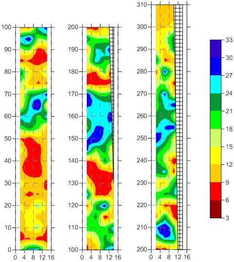
Thickness Plot
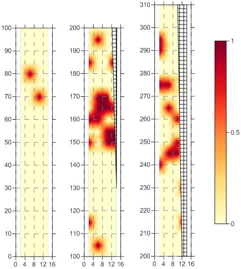
Delamination Plot